Energy-saving cooling systems for injection molding machines
Energy-saving cooling systems for high-performance injection molding
machines are needed to reduce the energy consumption of powerful
cooling systems. It is thanks to such installations that it is possible to
substantially reduce the operating costs of cooling and improve the quality of
production as a whole. Industrial processes require large volumes of cold
water, the temperature of which must remain stable for a long time. In
such cases, you can use free coolers (dry cooling towers).
Drycoolers or dry coolers are water-air heat exchangers that provide cooling of
water through ambient air passing through the heat exchanger plates with the
help of axial fans. At the same time, energy consumption is significantly
lower compared to compressor coolers. Therefore, in those processes where
possible, free coolers are used instead of compressor-based chillers, which
leads to a reduction in running costs.
Free-coolers have a huge cooling potential in the cold season, and therefore
they are widely used in energy-efficient centralized cooling systems.
Total energy saving
When the required water temperature is always above the ambient temperature,
the free cooler can operate year-round, providing greater energy savings
compared to water chillers.
Partial energy savings
When the required water temperature is below ambient temperature (in summer),
the freecooler must be used in conjunction with a water chiller. In this
case, energy savings are possible only in cold weather, and depend on the
geographical location and the required water temperature.
Calculation of energy savings
An estimate of energy savings is possible when the annual values of the
ambient temperature (for a specific geographic area) and the number of hours of
operation per year are known. Based on the specific temperature of the
working water and working time during the year, it is possible to calculate the
energy consumption, the comparative costs for the free cooler and the water
chiller.
These calculations provide a very reliable basis for evaluating the payback of
equipment.
Example No. 1 refers to the systems shown
in Figures 1 and 3 below.
Cooling of one circuit is
required . Required cooling capacity: 200
kW
Water temperature: 15 ° C
Region: Moscow region
Average duty cycle of free cooler per circuit (cold): 67% time
Energy savings: 256 850 kWh or 65%.
Example No. 2 refers to the system shown in Figure 2
below.
It is necessary to cool the two
LTC circuits (low-temperature circuit) - the required cooling
capacity of 80 kW at a water temperature of 15 ° C
HTC (high- temperature loop) - required cooling capacity 120 kW at 33 ° C water
temperature
Region: Kiev region Freecooler
cycle for HTC circuit - 100% of the time
Energy saving: 300,000 kWh per year, or 76%
As a result, the energy-saving cooling system pays off for a period of two to
n years, depending on the specifics of production.
As a rule, any existing cooling system can be equipped with additional
equipment to ensure the advantages of energy-saving systems.
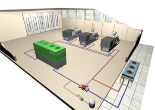
Cooling TPA single-circuit scheme
The system has one circuit for cooling hydraulic drives and molds
TPA.
Applicable with water temperature limitations for hydraulics cooling 20-25 °
C
|
Figure 1.1
|
Figure 1.2
|
| "Summer" - normal operation: Compressor cooler - on, cooling circuit Dry cooler - off Three-way valve - dry cooler is excluded from the circuit |
"Winter" - energy saving mode of
operation: Compressor cooler - pump on, compressors off Dry cooler - on, circuit cooling Three-way valve - dry cooler included in the circuit |

Cooling TPA two-circuit scheme
The system has two circuits: for cooling hydraulic drives and cooling molds TPA.
It is used with water temperature limitations for hydraulics cooling up to 35-40ºС.
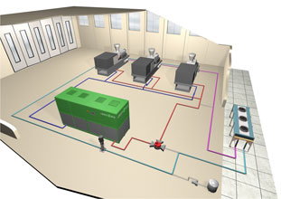 Figure 2.1
|
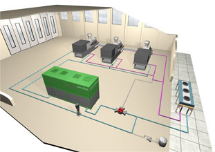 Figure 2.2
|
| "Summer" - normal operation mode: Compressor cooler: switched on cooling of the mold circuit Dry cooler: switched on for cooling of the hydraulic circuit Three-way valve: the circuits are separated |
"Winter" - energy-saving operation
mode: Compressor cooler: pump on, compressors off Dry cooler: switched on for cooling of both circuits Three-way valve: the circuits are combined |
Cooling the baths of extrusion lines
The system has one circuit for cooling the distribution tank.
The cooler does not have its own pump. One pump is installed at the outlet of the tank.
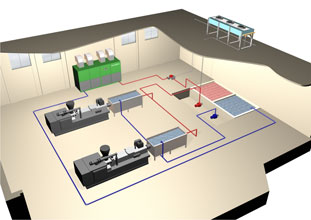 Figure 3.1.
|
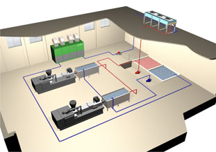 Figure 3.2
|
| "Summer" - normal operation: Compressor cooler - on, cooling circuit Dry cooler - off Three-way valve - dry cooler is excluded from the circuit |
"Winter" - energy saving mode of
operation: Compressor cooler - pump on, compressors off Dry cooler - on, circuit cooling Three-way valve - dry cooler included in the circuit |